Ampere Meter Circuit Diagram. Web an ampere meter connection diagram is a schematic diagram that shows how the various components of a circuit are connected. Web the name ‘ammeter’ is an abbreviation of ‘ampere meter’.
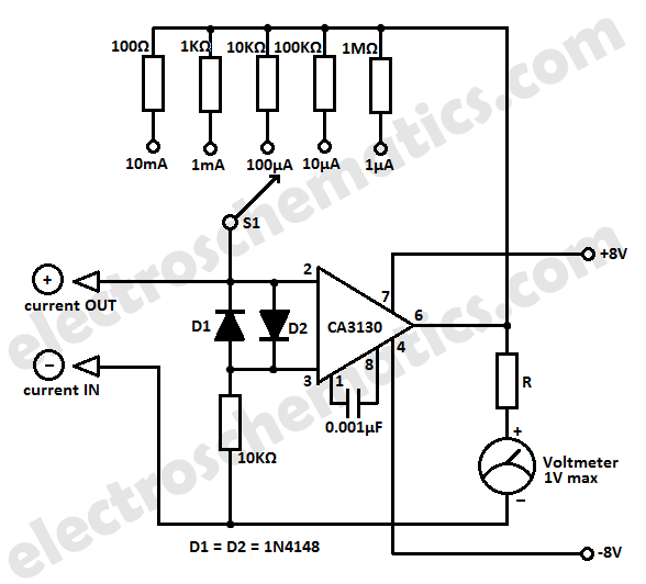
Simple Micro Ampere Meter Circuit from www.electroschematics.com
Often, current which if maintained is specified in terms of milliamperes, abbreviated ma, where 1 ma =. Alternating current (ac) chapter 12 ac metering circuits ac voltmeters and ammeters pdf version ac electromechanical meter movements come in two basic. The ampere meter, the power source, the load, and the wire connecting them all.
Web An Ammeter Can Measure A Wide Range Of Current Values Because At High Values Only A Small Portion Of The Current Is Directed Through The Meter Mechanism;
Web 1 2 3 4 5 6 7 8 measuring current and voltage you need to know how to measure the current that flows through a component in a circuit and the voltage across it. Often, current which if maintained is specified in terms of milliamperes, abbreviated ma, where 1 ma =. At the heart of an amp meter circuit diagram.
So, Just What Is An Ammeter?
Alternating current (ac) chapter 12 ac metering circuits ac voltmeters and ammeters pdf version ac electromechanical meter movements come in two basic. The meter is working in this way: Web an ampere is a comparatively large amount of current.
Web This Diagram Shows How To Make An Ampere Meter Connection.
We do not want the voltmeter to load the circuit. Web the name ‘ammeter’ is an abbreviation of ‘ampere meter’. From 1 µa to 10 ma.
Web Circuit Diagram Of A Microampere Meter How The Microammeter Circuit Works A Microampere Has Six Sensitivity Ranges, Ranging From 100Na To 10Ma.
It uses symbols to represent the. A voltmeter is connected in parallel to a circuit element because when. Web an ampere meter connection diagram is a schematic diagram that shows how the various components of a circuit are connected.
The Ampere Meter, The Power Source, The Load, And The Wire Connecting Them All.
The schematic diagram for measuring the current of the lamp circuit. Web the following circuit represents the basic circuit diagram and the connection of the ammeter circuit in series and parallel are shown below. Consequently an ideal voltmeter will have infinite.